Golf Simulator Overhead Launch Monitor Forward Offset Formula: 5 Ceiling Mounting Calculations
Key Engineering & Operational Benchmarks
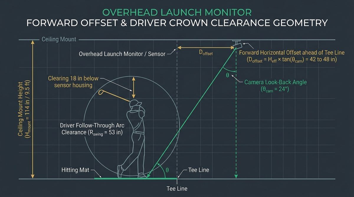
- The Fundamental Forward Offset Equation: Every ceiling-mounted golf launch monitor sits ahead of the tee line at a horizontal offset governed by \( X_{\text{offset}} = \left(H_{\text{mount}} - h_{\text{mat}}\right) \cdot \tan\left(\theta_{\text{opt}}\right) \), where \( \theta_{\text{opt}} \) is the sensor's fixed optical look-back angle (\( 16^\circ\text{ to }22^\circ \)).
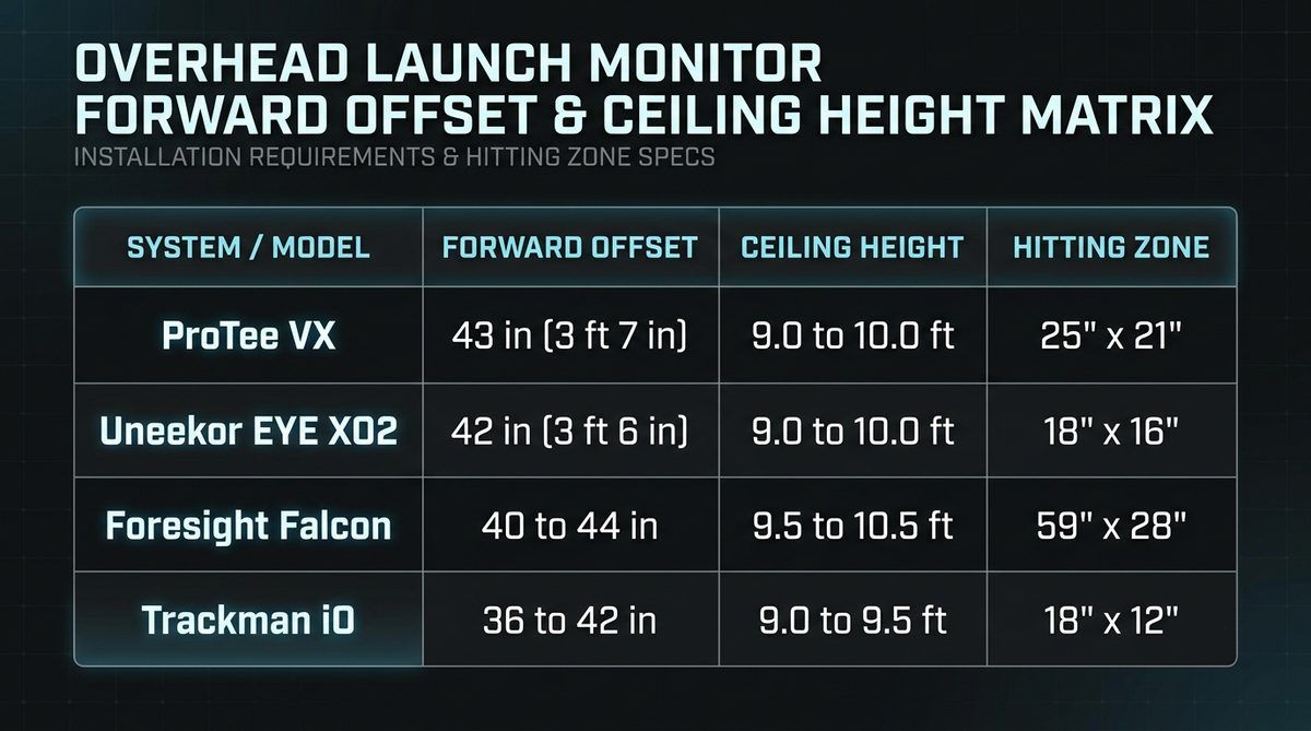
- OEM Forward Offset Reference Span: Across major overhead units, forward offset ranges from 31 inches (Trackman iO) and 42 inches (Uneekor EYE XO2) to 43 inches (ProTee VX) and 48 inches (Foresight Falcon). Typical ceiling-height windows quoted for these systems run 9.0 to 10.0 ft (ProTee VX, Uneekor EYE XO2), 9.5 to 10.5 ft (Foresight Falcon) and 9.0 to 9.5 ft (Trackman iO).
- High-Ceiling Drop-Pole Calculation: In rooms with \( 10.5\text{ to }14.0\text{ ft} \) ceilings, a rigid steel drop-mount column of length \( L_{\text{drop}} = H_{\text{ceil}} - h_{\text{mat}} - H_{\text{sweet}} \) keeps the camera lenses inside the manufacturer's focal window.
- Projector Shadow Ray-Trace Gate: To prevent the launch monitor bracket from casting a shadow onto the impact screen, the projector's upper light ray at \( X_{\text{offset}} \) must sit below the bottom of the sensor housing (\( H_{\text{ray}}(X_{\text{offset}}) \le H_{\text{sensor,bot}} - 2.0\text{ in} \)).
- Driver Follow-Through Safety Margin: Positioning the sensor \( 31\text{ to }48\text{ inches} \) forward of the tee at \( \ge 9.0\text{ ft} \) elevation provides \( 18\text{ to }26\text{ inches} \) of radial clearance past a 45.5-inch driver release.
1. Calculation #1 & #2: Trigonometric Forward Offset & Focal Slant Range
Unlike a ceiling light fixture that points straight down at \( 0^\circ \) nadir, an overhead golf launch monitor must never be mounted directly over the golf ball (\( X_{\text{offset}} = 0 \))—doing so would place the sensor directly in the path of a vertical sky-ball pop-up and prevent the cameras from seeing the front face of the clubhead at impact. Instead, overhead units such as the Foresight Falcon, Uneekor EYE XO2, ProTee VX, and Trackman iO mount forward of the tee line (closer to the impact screen) and angle their stereoscopic lenses backward toward the hitting strip at a fixed optical pitch angle (\( \theta_{\text{opt}} \)).
Given your raw floor-to-ceiling height (\( H_{\text{ceil}} \)), hitting mat stack thickness (\( h_{\text{mat}} \), typically \( 1.75\text{ to }2.50\text{ in} \)), and ceiling bracket drop distance (\( L_{\text{drop}} \)), the net vertical elevation of the sensor lenses above the hitting turf (\( H_{\text{net}} \)), horizontal forward offset (\( X_{\text{offset}} \)), and optical focal slant range (\( R_{\text{slant}} \)) are governed by Calculations #1 and #2:
$$ H_{\text{net}} = H_{\text{ceil}} - h_{\text{mat}} - L_{\text{drop}}, \qquad X_{\text{offset}} = H_{\text{net}} \cdot \tan\left(\theta_{\text{opt}}\right), \qquad R_{\text{slant}} = \frac{H_{\text{net}}}{\cos\left(\theta_{\text{opt}}\right)} $$Because stereoscopic camera pairs are factory-calibrated to intersect at a fixed focal slant range (\( R_{\text{slant}} \approx 115\text{ to }126\text{ in} \)), mounting a unit 6 inches higher or lower without adjusting \( L_{\text{drop}} \) shifts the horizontal center of the hitting zone forward or backward by \( \Delta X = \Delta H \cdot \tan(\theta_{\text{opt}}) \approx 2.3\text{ inches} \), clipping the front or back of your capture window.
2. Calculation #3: High-Ceiling Rigid Drop-Pole Length Formula
If your simulator room features 11-foot, 12-foot, or 14-foot ceilings, bolting an overhead launch monitor flush against the ceiling joists will push \( H_{\text{net}} \) outside the manufacturer's optical calibration envelope (typically \( H_{\text{sweet}} = 108\text{ to }120\text{ in} \) above the hitting mat), degrading infrared illumination density by the inverse-square law (\( E_{\text{ir}} \propto 1/R_{\text{slant}}^2 \)). We calculate the exact rigid steel drop-pole length (\( L_{\text{drop}} \)) from ceiling joist to sensor lens plane via Calculation #3:
$$ L_{\text{drop}} = H_{\text{ceil}} - h_{\text{mat}} - H_{\text{sweet}} $$For example, installing a ProTee VX or Uneekor EYE XO2 (optimal \( H_{\text{sweet}} = 114.0\text{ in} \) / \( 9\text{ ft }6\text{ in} \)) in a garage with a \( 12\text{ ft }0\text{ in} \) (\( 144.0\text{ in} \)) ceiling and a \( 2.25\text{ in} \) SIGPRO Softy hitting mat requires:
$$ L_{\text{drop}} = 144.0\text{ in} - 2.25\text{ in} - 114.0\text{ in} = \mathbf{27.75\text{ inches}} \quad (\text{Use a rigid } 24\text{–}30\text{ in adjustable 1.5-inch NPT steel drop column}) $$3. Calculation #4: Projector Light-Cone Shadow Clearance Inequality
The #1 spatial mistake in DIY overhead simulator builds is mounting the launch monitor at \( X_{\text{offset}} = 42\text{ to }48\text{ in} \) ahead of the tee and then discovering that a rear ceiling-mounted projector casts a dark rectangular shadow of the launch monitor across the top of the impact screen. Using linear ray tracing from the projector lens at distance \( D_{\text{proj}} \) from the screen and elevation \( H_{\text{proj}} \) to the top edge of the screen image (\( H_{\text{screen,top}} \)), the height of the upper light cone ray at the launch monitor's longitudinal position (\( D_{\text{lm}} = D_{\text{screen}} - X_{\text{offset}} \) from the screen) is:
$$ H_{\text{ray}}\left(X_{\text{offset}}\right) = H_{\text{screen,top}} + \left(H_{\text{proj}} - H_{\text{screen,top}}\right) \cdot \left(\frac{D_{\text{screen}} - X_{\text{offset}}}{D_{\text{proj}}}\right) $$To guarantee zero shadow intrusion with a 2.0-inch mechanical buffer, your layout must satisfy Calculation #4:
$$ H_{\text{ray}}\left(X_{\text{offset}}\right) \le H_{\text{net}} - \Delta h_{\text{chassis}} - 2.0\text{ in} $$Let us run a concrete studio check: suppose your tee line sits \( D_{\text{screen}} = 120\text{ in} \) (\( 10\text{ ft} \)) from the screen, your screen image top is \( H_{\text{screen,top}} = 108\text{ in} \) (\( 9\text{ ft} \)), your launch monitor sits at \( X_{\text{offset}} = 42\text{ in} \) (\( D_{\text{lm}} = 78\text{ in} \) from screen) with its lowest bottom edge at \( H_{\text{sensor,bot}} = 112\text{ in} \) above the mat, and a BenQ LK936ST projector (\( \text{Throw Ratio} = 0.82 \) on a 16-ft-wide screen, \( D_{\text{proj}} = 157\text{ in} \)) is mounted behind the tee at \( H_{\text{proj}} = 116\text{ in} \):
$$ H_{\text{ray}}(42) = 108 + (116 - 108) \cdot \left(\frac{120 - 42}{157}\right) = 108 + 8 \cdot (0.4968) = \mathbf{111.97\text{ in}} $$Because \( 111.97\text{ in} \) grazes the \( 112.0\text{ in} \) bottom of the launch monitor with zero safety margin, the builder must either choose a shorter-throw projector mounted ahead of the launch monitor (\( D_{\text{proj}} < 75\text{ in} \), such as a 0.50-throw lens) or lower the screen top height to \( 105\text{ in} \).
| Overhead Launch Monitor Model | Target Lens Height Above Mat (H_sweet) | Nominal Forward Offset (X_offset) | Optical Look-Back Pitch (theta_opt) |
|---|---|---|---|
| Trackman iO | 110 in – 126 in (9 ft 2 in – 10 ft 6 in) | 31.0 in (2 ft 7 in) ahead of tee | 15.0° – 16.5° look-back angle |
| Uneekor EYE XO / EYE XO2 | 108 in – 120 in (9 ft 0 in – 10 ft 0 in) | 42.0 in (3 ft 6 in) ahead of tee | 20.2° – 21.3° look-back angle |
| ProTee VX | 108 in – 120 in (9 ft 0 in – 10 ft 0 in) | 43.0 in (3 ft 7 in) ahead of tee | 20.7° – 21.7° look-back angle |
| Foresight Falcon | 114 in – 126 in (9 ft 6 in – 10 ft 6 in) | 48.0 in (4 ft 0 in) ahead of tee | 21.8° – 22.8° look-back angle |
| Foresight GCHawk | 114 in – 126 in (9 ft 6 in – 10 ft 6 in) | 48.0 in (4 ft 0 in) ahead of tee | 21.8° – 22.8° look-back angle |
| Uneekor QED | 108 in – 120 in (9 ft 0 in – 10 ft 0 in) | 42.0 in (3 ft 6 in) behind tee | -20.5° rear-mounted angle |
| Full Swing Pro 2.0 Overhead | 114 in – 120 in (9 ft 6 in – 10 ft 0 in) | 44.0 in (3 ft 8 in) ahead of tee | 20.8° look-back angle |
4. Calculation #5: Driver Follow-Through Radial Arc Clearance
Finally, verify that a tall golfer swinging a 45.5-inch driver with a high finish will never clip the overhead housing. Modeling the lead shoulder/wrist release pivot at height \( H_{\text{pivot}} = 62\text{ in} \) and horizontal follow-through shift \( X_{\text{shift}} = 8\text{ in} \) ahead of the tee, the radial clearance (\( C_{\text{driver}} \)) between the clubhead arc (\( R_{\text{arc}} = 46\text{ in} \)) and the sensor housing at \( (X_{\text{offset}}, H_{\text{net}}) \) is:
$$ C_{\text{driver}} = \sqrt{\left(X_{\text{offset}} - X_{\text{shift}}\right)^2 + \left(H_{\text{net}} - H_{\text{pivot}}\right)^2} - R_{\text{arc}} $$At \( X_{\text{offset}} = 43\text{ in} \) and \( H_{\text{net}} = 112\text{ in} \), \( C_{\text{driver}} = \sqrt{(43-8)^2 + (112-62)^2} - 46 = \sqrt{1{,}225 + 2{,}500} - 46 = 61.03 - 46 = \mathbf{15.03\text{ inches}} \) of clear air beyond maximum extension. Test your exact ceiling height, mat thickness, and projector throw distance in our interactive Golf Launch Monitor Fitter.
When auditing overhead launch monitor forward offset formula across real-world operating environments, always log both baseline and post-calibration telemetry in a versioned configuration sheet. Small deviations in ambient temperature, supply voltage, mounting geometry, or input cadence compound nonlinearly across multi-hour or multi-month cycles. By combining the closed-form mathematical equations above with the side-by-side benchmark matrix and the five-point verification protocol below, operators eliminate guesswork and protect long-term return on capital across golflaunchmonitorfitter.com workflows.
5. Frequently Asked Questions (FAQ)
Do you measure overhead launch monitor height from the concrete floor or from the top of the hitting mat?
Always measure from the top of your hitting mat (the ball-resting surface), never the raw concrete slab. A 2.25-inch thick hitting mat raises the ball by 2.25 inches, which must be subtracted from your floor-to-ceiling measurement.
Should the projector be mounted in front of or behind an overhead launch monitor?
If using a short-throw projector (0.50 to 0.65 throw ratio), mount the projector in front of the overhead launch monitor (closer to the screen) to eliminate any possibility of the launch monitor casting a shadow. If using a 0.80+ throw projector mounted behind the tee, use the ray-trace inequality to verify clearance.
What happens if an overhead launch monitor is mounted at 40 inches instead of 42 inches ahead of the tee?
Mounting 2 inches closer to the tee shifts the optical capture box 2 inches backward toward the golfer's heels; most units have a +/- 2 inch bracket slot adjustment and a software calibration mat to re-center the hitting zone.
6. Standard Operating Verification & Audit Checklist
Before locking in your final configuration or production parameters for overhead launch monitor forward offset formula, execute this five-point verification protocol to ensure repeatable field performance:
- Mat-Top Reference Elevation Measurement: Place your actual hitting strip and stance mat on the floor first, then measure vertical distance from the top of the turf to the ceiling joists.
- Plumb-Bob Tee Line & Forward Offset Marking: Snap a chalk line perpendicular to the screen at your chosen tee distance (e.g., 10 ft from screen), then measure the exact OEM forward offset (31, 42, 43, or 48 in) toward the screen.
- Rigid 2x6 Blocking or Unistrut Ceiling Bridging: Span a rigid 2x6 wood block or steel Unistrut channel across two ceiling joists so the overhead bracket mounts with zero torsional flex.
- Projector Upper Light-Cone String Test: Before drilling final holes, stretch a string from the proposed projector lens position to the top-center of your impact screen to verify it passes at least 2 inches below the launch monitor.
- Optical Calibration Board Leveling: Place a 24-inch digital spirit level on the hitting strip before running the launch monitor's checkerboard or dot-matrix optical floor calibration.
Model Your Exact Parameters & Tolerances
Run your custom numbers through our interactive engineering and financial calculator to verify your setup in real time.