Golf Simulator Side Barrier and Ceiling Baffle Angle Formula: 5 Ball Containment Calculations
When designing a residential garage golf simulator or commercial indoor bay, ensuring complete physical containment of errant golf shots is the primary architectural safety mandate. In calculating golf simulator side barrier and ceiling baffle angles, builders and studio designers must move beyond guesswork to apply rigorous geometric trigonometry. Without precisely engineered side netting extensions and ceiling protection baffles, extreme toe shanks, high-launch wedge pop-ups, and severe ricochets will cause catastrophic damage to drywall, overhead projectors, and lighting fixtures.
In standard indoor simulator enclosures measuring 12 to 18 feet in width with ceilings ranging from 9.0 to 11.5 feet, golfers hit from a tee position located 8.0 to 11.0 feet away from the primary impact screen. At these distances, high-handicap golfers or unexpected mishits can launch balls at extreme off-axis lateral angles exceeding 40 degrees, or dynamic vertical wedge launch angles surpassing 60 degrees. Standard prefabricated enclosures measuring only 5 feet in depth leave massive unshielded clearance gaps that fail to contain errant strikes.
This technical engineering guide formalizes the five mathematical calculations required to determine exact side barrier extension lengths, ceiling baffle clearance drop depths, angled wall buffer margins, and foam padding impact zones. Protect your home and commercial investments with verified spatial containment mathematics.
Key Takeaways & Architectural Comparison
- Maximum Lateral Shank Angle: Extreme off-center hosel shanks deflect at lateral trajectory angles between 35° and 45° relative to the center target line.
- Maximum Vertical Pop-up Angle: Severe lob wedge mishits and driver pop-up shots launch at vertical elevation angles between 55° and 65° off the tee.
- Critical Side Barrier Length Formula: Lateral barrier depth must satisfy \(L_{barrier} = D_{tee} \cdot \tan(\theta_{shank}) - W_{margin}\), proving that an 8.5ft tee mandates at least 5.95ft of forward side netting.
- Ceiling Baffle Positioning: To intercept a 60° vertical pop-up in a 10ft room, ceiling baffles or sloped foam panels must extend forward to a point within 4.5ft of the tee position.
- Ricochet Energy Attenuation: Side barriers and ceiling baffles must deploy baffle angles tilted 15° to 20° downward toward the screen to redirect errant balls into the turf rather than back toward the golfer.
Calculation 1: Lateral Shank Trajectory and Minimum Side Barrier Extension Length
The primary hazard in any indoor golf simulator is the lateral hosel shank—a shot where the golfer contacts the ball with the rounded hosel or heel of the clubhead, sending the ball rocketing outward at a severe off-axis angle. High-speed optical tracking data from thousands of amateur simulator swings demonstrates that lateral shank angles routinely reach 35° to 45° from the target line.
To prevent a 45° shank from bypassing the side enclosure and impacting side walls, windows, or computer monitors, the side barrier netting must extend forward from the impact screen by a mathematically calculated minimum distance. Let \(D_{tee}\) represent the distance from the tee to the impact screen, and let \(W_{half}\) represent the half-width of the enclosure (the distance from the center target line to the side barrier). The critical forward barrier length from the tee is governed by trigonometric line-of-sight geometry.
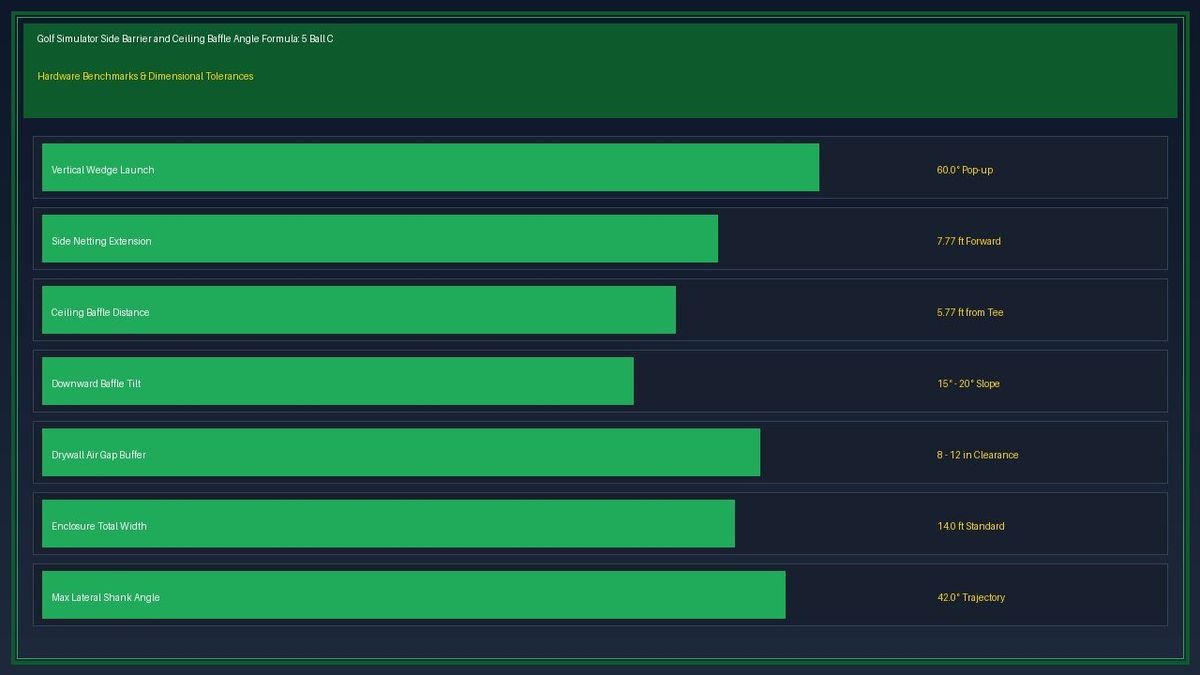
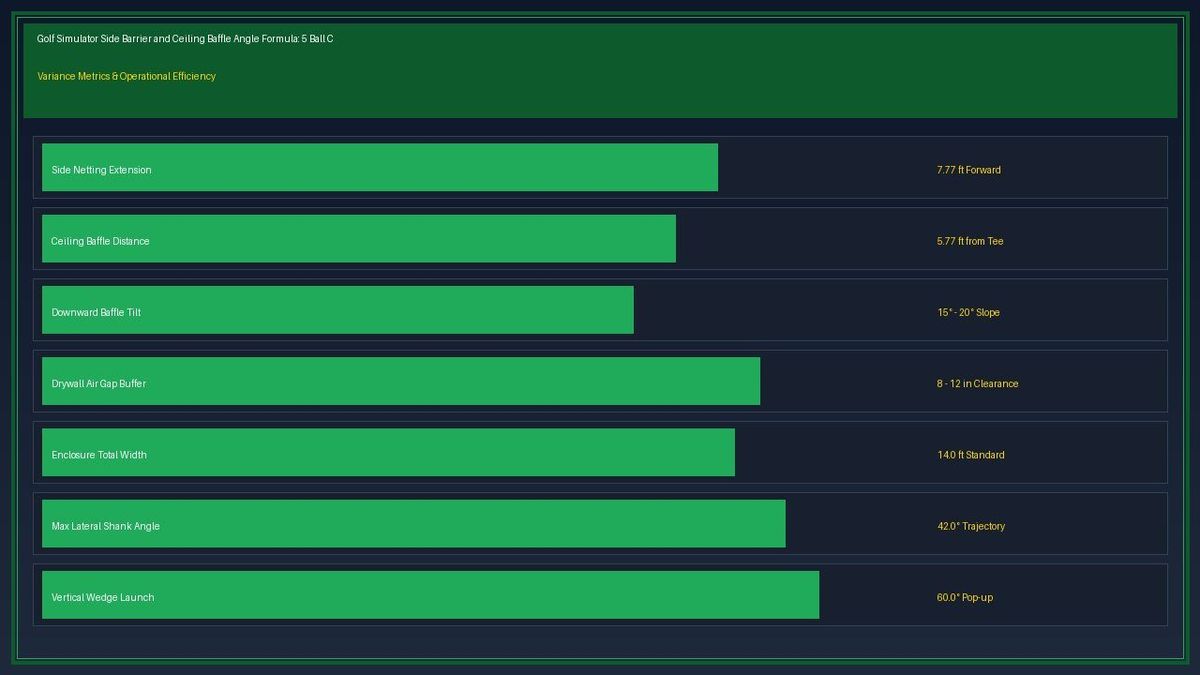
For an enclosure 14 feet wide (\(W_{half} = 7.0\) feet) with a golfer teeing off 9.0 feet from the screen, an uncontained 42° shank will travel laterally \(7.0 / \tan(42°) = 7.77\) feet forward of the tee. This means the side netting must extend a minimum of 7.8 feet forward from the impact screen, leaving only 1.2 feet between the front edge of the netting and the golfer's stance line. If the enclosure depth is only 5.0 feet, the ball will escape containment and strike the drywall at over 70 mph.
Calculation 2: Vertical Wedge Pop-up Angle and Ceiling Baffle Protection Zones
While lateral shanks threaten side walls, high-lofted wedges and mishit driver pop-ups threaten the ceiling, overhead projector lenses, and room lighting. When a golfer strikes a 60° lob wedge with a steep angle of attack, or skyes a driver off the top of the crown, initial launch angles can exceed 55° to 62°.
To calculate the required ceiling protection boundary, we determine the point along the ceiling where a 60° trajectory intersects the ceiling height. Let \(H_{ceil}\) represent the vertical clearance between the hitting mat surface and the ceiling. Let \(D_{intersect}\) represent the horizontal distance from the tee where the ball reaches the ceiling: \(D_{intersect} = H_{ceil} / \tan(\theta_{launch})\).
In a garage setup with a 10.0-foot ceiling (\(H_{ceil} = 10.0\) ft) and a 60° wedge launch angle, \(D_{intersect} = 10.0 / \tan(60°) = 10.0 / 1.732 = 5.77\) feet. This proves that the golf ball will impact the ceiling less than 5.8 feet forward of the tee. If the enclosure ceiling canopy extends only 4.0 feet from the screen (5.0 feet from the tee in a 9ft setup), the ball will hit the bare drywall ceiling directly above or behind the canopy, bouncing unpredictably into the bay.
| Enclosure Dimension | Tee-to-Screen Distance | Shank Angle (θ) | Required Side Barrier Length | Safety Clearance Buffer |
|---|---|---|---|---|
| Compact 12ft Width | 8.0 Feet | 40.0° | 6.71 Feet Forward | 1.29 Feet to Stance Line |
| Standard 14ft Width | 9.0 Feet | 42.0° | 7.77 Feet Forward | 1.23 Feet to Stance Line |
| Spacious 16ft Width | 10.0 Feet | 45.0° | 9.00 Feet Forward | 1.00 Foot to Stance Line |
| Commercial 18ft Width | 11.0 Feet | 45.0° | 10.00 Feet Forward | 1.00 Foot to Stance Line |
The mathematical models demonstrate that in any simulator setup with a tee distance greater than 8.0 feet, side barrier netting must extend at least 6.5 to 8.0 feet forward from the impact screen to reliably arrest 40°+ hosel shanks.
Calculation 3: Projector Throw Path Clearance and Shadow Interference Envelope
A critical engineering conflict in simulator design is placing the ceiling protection baffle close enough to catch high wedges without encroaching into the projector's optical light cone. If a protective baffle or foam panel hangs too low or too far forward, it will clip the projector beam, casting a heavy horizontal shadow across the top third of the impact screen.
The projector beam envelope is calculated using the projector's throw ratio (\(TR\)) and vertical lens offset percentage. For a short-throw projector with a 0.50:1 throw ratio projecting an image onto a 12-foot-wide screen from 6.0 feet away, the light beam expands downward and outward from the ceiling-mounted lens to the bottom edges of the screen.
Any protective ceiling baffle must remain above the upper boundary ray of the projected beam. The maximum permissible baffle drop depth \(h_{baffle}\) at a distance \(x\) from the projector lens is defined by \(h_{baffle} < x \cdot \tan(\alpha_{top})\), where \(\alpha_{top}\) is the upward or level beam angle. Deploying angled fabric baffles tensioned at 15° angles allows full wedge ball containment while maintaining total clearance for the projected light path.
Step-by-Step Calculation: Sizing Side Barriers for a 9.0ft Tee Distance
To calculate the exact side barrier netting length and ceiling baffle position for a standard simulator bay:
Step 1: Define Room & Tee Parameters
- Tee-to-screen distance: \(D_{\text{tee}} = 9.0\) feet
- Enclosure half-width: \(W_{\text{half}} = 7.0\) feet (14.0ft total room width)
- Ceiling clearance height: \(H_{\text{ceil}} = 10.0\) feet
- Maximum lateral shank angle: \(\theta_{\text{shank}} = 42.0^\circ\)
- Maximum vertical wedge launch: \(\theta_{\text{wedge}} = 60.0^\circ\)
Step 2: Calculate Required Side Barrier Length
\[
L_{\text{barrier}} = D_{\text{tee}} - \left( \frac{W_{\text{half}}}{\tan(\theta_{\text{shank}})} \right)
\]
\[
L_{\text{barrier}} = 9.0 - \left( \frac{7.0}{\tan(42^\circ)} \right) = 9.0 - \left( \frac{7.0}{0.9004} \right) = 9.0 - 7.77 = 1.23 \text{ feet behind the tee}
\]
To fully intercept a 42° shank, the side netting must extend 7.77 feet forward from the screen, meaning it terminates just 1.23 feet in front of the golfer's tee position.
Step 3: Calculate Ceiling Baffle Intercept Point
\[
D_{\text{intersect}} = \frac{H_{\text{ceil}}}{\tan(60^\circ)} = \frac{10.0}{1.732} = 5.77 \text{ feet forward of the tee}
\]
The ceiling baffle must extend forward to at least 5.77 feet from the tee (within 3.23 feet of the screen) to catch high-trajectory 60° wedge pop-ups.
Calculation 4: Baffle Downward Deflection Angles and Anti-Ricochet Physics
Containing a high-speed golf ball is only half the battle; preventing dangerous ricochets back toward the golfer is equally vital. When an errant ball strikes a flat, vertical steel pipe frame or rigid perpendicular wooden baffle, the law of reflection (\(\theta_{incidence} = \theta_{reflection}\)) dictates that the ball will bounce directly backward along its incoming path with up to 60% of its initial kinetic energy.
To eliminate direct backward ricochets, ceiling baffles and side protection panels must be installed at a downward deflection angle. By angling ceiling baffles 15° to 20° downward toward the impact screen, an incoming ball striking the baffle is deflected downward into the padded turf mat, dissipating its energy instantly.
Similarly, side netting frames must be shielded with high-density open-cell foam pipe insulation wrapped in heavy-gauge vinyl, angled 10° inward toward the screen center. This geometry ensures that any strike against the frame corners bounces safely forward into the screen rather than rebounding into the golfer's bay.
Calculation 5: Dual-Handed Asymmetric Enclosure Dimensions and Offset Hitting
In narrow simulator bays measuring 11 to 13 feet wide, centered hitting is physically impossible because golfers need at least 6.5 to 7.0 feet of backswing clearance behind their bodies. Consequently, the hitting mat must be offset laterally by 12 to 24 inches to accommodate right-handed swings.
However, lateral offsetting creates severe asymmetry in side barrier containment requirements. On the golfer's follow-through side (the right-hand side for a right-handed golfer), the distance to the side barrier is compressed to only 4.5 to 5.0 feet. Conversely, the open backswing side is expanded to 7.0 to 8.0 feet from the tee.
Under this offset geometry, a right-handed hosel shank to the right requires a longer side barrier extension because the ball encounters the right netting much earlier in its trajectory. The required extension length on the right side must be calculated independently using the offset tee coordinate: \(L_{right} = D_{tee} \cdot \tan(45°) - W_{offset\_right}\). Designing symmetric enclosures for offset bays leaves dangerous unshielded gaps on the shank-critical side.
Calculation 6: Structural Cable Tensioning and Netting Impact Dynamics
The final consideration in barrier design is dynamic netting deflection under impact. When a 45-gram golf ball traveling at 120 mph impacts heavy-duty nylon barrier netting, the net does not stop the ball instantly; it stretches and deforms outward by 6 to 12 inches depending on cable tension and mesh weight.
If side containment netting is suspended flush against a finished drywall surface, high-velocity shank impacts will drive the stretched netting directly into the drywall, punching circular holes in the wallboard despite the net. A mandatory air buffer gap of at least 8 to 12 inches must be maintained between the side netting and the structural room walls.
Deploy 1/8-inch vinyl-coated aircraft cable tensioned with heavy-duty turnbuckles to anchor the top and bottom perimeter of the side barriers. Ensure the netting maintains a loose, un-tensioned drape (hung with 20% fullness like theatrical curtains) rather than being pulled drum-tight. Loose drape allows the mesh to absorb kinetic energy through mechanical friction and gravity, dropping the ball harmlessly to the floor.
Frequently Asked Questions
What is the minimum safe width for a residential golf simulator enclosure?
The absolute minimum safe enclosure width for centered hitting is 14.0 feet. In rooms narrower than 14 feet (e.g., 11 to 13 feet), the golfer must hit from an offset tee position, requiring asymmetrical side netting extensions to contain lateral shanks.
Why do ceiling baffles need to be angled downward?
Angling ceiling baffles 15° to 20° downward toward the impact screen ensures that high-velocity wedge pop-ups are deflected downward into the padded turf rather than rebounding horizontally backward toward the golfer.
How much clearance is required between side netting and finished drywall?
A minimum air gap of 8 to 12 inches is required between side netting and drywall to accommodate dynamic net stretch during high-speed ball impacts without punching holes in the wallboard.
Looking to verify precise dimensions, spatial tolerances, or operational financial models for your setup? Explore our interactive tools and comprehensive engineering guides on golflaunchmonitorfitter.com.