Golf Simulator Projector Throw Ratio and Vertical Lens Shift Drop Formula: 5 Optical Geometry Calculations
Installing a projector inside a residential golf simulator bay involves far tighter geometric tolerances than setting up a standard home theater. In a golf simulator, the optical projection beam must fill an impact screen measuring 10 to 16 feet wide, avoid throwing shadows when a 6-foot golfer completes a high follow-through swing, remain protected from high-velocity wedge ricochets, and align vertically with the ceiling mount without relying on image-degrading digital keystone correction. Miscalculating projector placement by even 6 inches can result in permanent shadow obstruction or an undersized image that fails to fill your impact enclosure.
To eliminate costly mounting errors, simulator builders must utilize precise optical geometry formulas. By calculating the exact throw distance from screen width and optical throw ratio, determining vertical lens drop from native offset percentages, and verifying golfer shadow clearance angles, you can lock in optimal projector placement before drilling a single hole in your ceiling. Below is the complete mathematical framework covering throw ratios, vertical lens shift offsets, shadow cutoffs, and screen illuminance thresholds.
Quick Optical Calculation Summary:
- Throw Distance Formula: \(D_{\text{throw}} = W_{\text{screen}} \times TR\), where \(W_{\text{screen}}\) is screen image width in feet and \(TR\) is the manufacturer lens throw ratio.
- Vertical Lens Offset Drop: \(D_{\text{drop}} = H_{\text{screen}} \times \left( \frac{\text{Offset}\% - 100\%}{100\%} \right)\) for ceiling-inverted projectors with fixed vertical offsets (e.g., 105% or 110%).
- Shadow Clearance Boundary: Golfer shadow is eliminated when the projector lens position is forward of the tee line or satisfies the angular elevation condition \(\theta_{\text{beam}} > \theta_{\text{golfer}}\).
- Illuminance Threshold: Impact screens require a minimum of \(E_{\text{screen}} \ge 250\text{ lux}\) (or \(\ge 75\text{ foot-lamberts}\)) to prevent ambient room light and hitting zone spotlights from washing out simulator graphics.
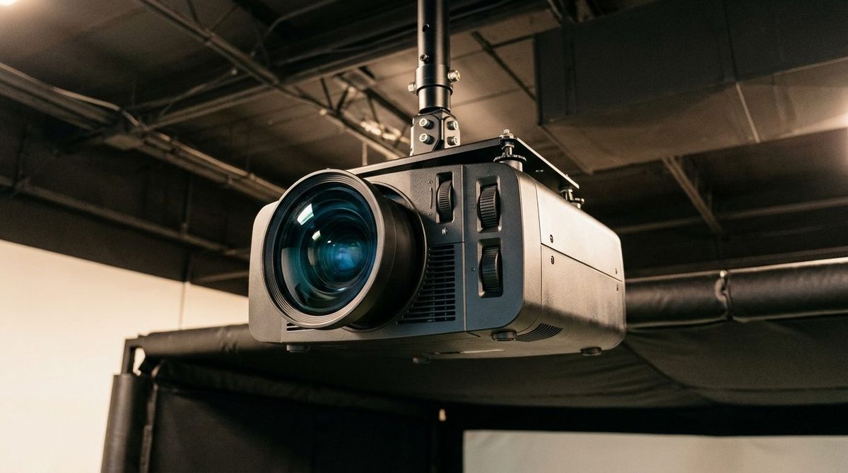
1. Calculation 1: The Core Throw Distance Equation
The primary calculation when selecting and positioning a golf simulator projector is determining the horizontal distance \(D_{\text{throw}}\) between the projector lens and the impact screen surface. Every projector lens is rated with an optical throw ratio (\(TR\)), defined as the ratio of throw distance to projected image width:
\[ TR = \frac{D_{\text{throw}}}{W_{\text{screen}}} \]Rearranging the equation to solve for required throw distance:
\[ D_{\text{throw}} = W_{\text{screen}} \times TR \]For example, consider a standard commercial impact screen with an image width of \(W_{\text{screen}} = 12.0\text{ feet}\) (144 inches). If an operator installs a popular short-throw laser projector like the BenQ LK936ST with a variable optical throw ratio of \(TR = 0.81\text{ to }0.89\), we compute the minimum and maximum mounting distances:
\[ D_{\text{throw, min}} = 12.0\text{ ft} \times 0.81 = 9.72\text{ ft} \quad (116.6\text{ in}) \] \[ D_{\text{throw, max}} = 12.0\text{ ft} \times 0.89 = 10.68\text{ ft} \quad (128.2\text{ in}) \]This 9.72 to 10.68-foot throw window allows the builder to place the projector safely behind the hitting enclosure buffer while keeping the optical beam forward of the golfer's swing path.
2. Calculation 2: Vertical Lens Shift and Inverted Ceiling Drop Distance
When a projector is inverted and mounted to the ceiling, the projected image does not emanate horizontally from the center of the lens. Instead, manufacturers build in an upward optical offset (which projects downward when inverted) so the projector can sit level with or above the top edge of the screen. We calculate the vertical distance \(D_{\text{drop}}\) from the center of the projector lens to the top border of the projected screen image:
\[ D_{\text{drop}} = H_{\text{screen}} \times \left( \frac{\text{Offset}\% - 100\%}{100\%} \right) \]Where \(H_{\text{screen}}\) is image height in inches, and \(\text{Offset}\%\) is the manufacturer's vertical offset rating. For a fixed-lens projector with a 110% offset throwing onto a 9-foot tall screen (\(H_{\text{screen}} = 108\text{ inches}\)):
\[ D_{\text{drop}} = 108\text{ in} \times \left( \frac{110\% - 100\%}{100\%} \right) = 108\text{ in} \times 0.10 = 10.8\text{ inches} \]This indicates that the projector lens must be mounted exactly 10.8 inches above the top edge of the projected white impact screen area. If the top edge of your screen sits at a height of 9.5 feet from the floor, the projector lens center must be positioned at \(9.5\text{ ft} + 0.90\text{ ft} = 10.40\text{ feet}\) above the floor. If your ceiling height is only 10.0 feet, you must select a projector with optical vertical lens shift (such as +/- 60% vertical shift) to bring the image down without tilting the chassis.
3. Calculation 3: Golfer Follow-Through Shadow Cutoff Geometry
The single most frustrating design flaw in DIY golf simulator builds is golfer shadow obstruction. When a golfer stands at the tee line and swings a driver, an improperly positioned projector casts the player's shadow directly onto the center of the impact screen. We determine the critical shadow cutoff boundary by modeling the light cone elevation angle \(\theta_{\text{beam}}\) from the bottom edge of the screen through the golfer's head height:
\[ \tan(\theta_{\text{beam}}) = \frac{H_{\text{lens}} - H_{\text{golfer}}}{D_{\text{tee}} - D_{\text{throw}}} \]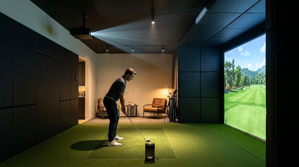
Where \(H_{\text{lens}}\) is ceiling lens height, \(H_{\text{golfer}}\) is the top of the golfer's swing arc (typically \(7.5\text{ feet}\) for a 6-foot golfer with a driver), \(D_{\text{tee}}\) is distance from impact screen to tee (typically \(10.0\text{ feet}\)), and \(D_{\text{throw}}\) is projector throw distance. To ensure zero shadow cast during both address and full follow-through:
- Rule A (Forward Mount): If \(D_{\text{throw}} < D_{\text{tee}}\) (for example, \(D_{\text{throw}} = 8.5\text{ ft}\) and \(D_{\text{tee}} = 10.0\text{ ft}\)), the projector is mounted forward of the golfer. Light projects entirely in front of the player, guaranteeing 100% zero shadow cast.
- Rule B (Rear Mount Clearance): If \(D_{\text{throw}} > D_{\text{tee}}\) (for example, \(D_{\text{throw}} = 13.0\text{ ft}\)), the lens height must satisfy:
4. Calculation 4: Aspect Ratio Dimensional Scaling and Resolution Matching
Impact screen dimensions rarely match standard video aspect ratios (16:9, 16:10, or 4:3). For instance, a garage with a 10-foot ceiling and 12-foot width creates an aspect ratio of \(12:10 = 1.20:1\), whereas standard 16:9 widescreen is \(1.78:1\). We calculate the active image width \(W_{\text{active}}\) and height \(H_{\text{active}}\) based on native resolution aspect ratio \(AR = \frac{W}{H}\):
\[ W_{\text{active}} = \min(W_{\text{enclosure}}, H_{\text{enclosure}} \times AR) \] \[ H_{\text{active}} = \frac{W_{\text{active}}}{AR} \]Table 1 details the active image dimensions and throw distances for an impact screen enclosure measuring 12 feet wide by 9 feet high across different projector aspect ratios using a short-throw lens with \(TR = 0.80\):
| Native Aspect Ratio | Resolution Example | Active Image Width | Active Image Height | Required Throw Distance | Screen Utilization |
|---|---|---|---|---|---|
| 16:9 (1.78:1) | 3840×2160 (4K UHD) | 12.0 ft (144 in) | 6.75 ft (81.0 in) | 9.60 ft (115.2 in) | 75.0% (Pillar bars top/bottom) |
| 16:10 (1.60:1) | 1920×1200 (WUXGA) | 12.0 ft (144 in) | 7.50 ft (90.0 in) | 9.60 ft (115.2 in) | 83.3% (Balanced coverage) |
| 4:3 (1.33:1) | 1024×768 (XGA) | 12.0 ft (144 in) | 9.00 ft (108.0 in) | 9.60 ft (115.2 in) | 100.0% (Full screen fill) |
5. Calculation 5: Screen Surface Illuminance and Foot-Lambert Thresholds
A golf simulator requires bright hitting zone illumination (typically 1,000 to 1,500 lux) so high-speed launch monitor cameras can track the ball dimples. If your projector lacks sufficient ANSI lumens, ambient light wash will degrade the contrast ratio to unplayable levels. We compute the peak screen illuminance \(E_{\text{screen}}\) in foot-lamberts (\(fL\)) and lux using the screen area formula:
\[ E_{\text{fL}} = \frac{\Phi_{\text{lumens}} \times G_{\text{screen}}}{A_{\text{screen, sqft}}} \] \[ E_{\text{lux}} = E_{\text{fL}} \times 10.764 \]Where \(\Phi_{\text{lumens}}\) is calibrated projector output, \(G_{\text{screen}}\) is impact screen material gain (typically \(0.85\) to \(0.95\) for durable multi-layer polyester mesh), and \(A_{\text{screen, sqft}}\) is image area in square feet. For a 12-foot by 9-foot screen (\(A = 108\text{ sq ft}\)) illuminated by a 5,000-lumen laser projector with a 0.90 gain impact screen:
\[ E_{\text{fL}} = \frac{5{,}000\text{ lumens} \times 0.90}{108\text{ sq ft}} = 41.67\text{ foot-lamberts} \] \[ E_{\text{lux}} = 41.67 \times 10.764 = 448.5\text{ lux} \]Because \(448.5\text{ lux} \ge 250\text{ lux}\), the projected image will maintain crisp 4K color saturation and contrast even with bay ceiling pin spotlights illuminated. To verify your complete simulator room blueprint, launch monitor positioning, and optical throw math, visit Golf Launch Monitor Fitter.
Calculate Your Exact Golf Simulator Optical Throw Blueprint
Input your room width, ceiling height, and projector specs to generate precise mounting diagrams at Golf Launch Monitor Fitter.
Access the Launch Monitor & Projector Calculator