Golf Simulator Pin Spotlight Beam Angle and Ceiling Baffle Glare Cutoff Formula: 5 Optical Lighting Calculations
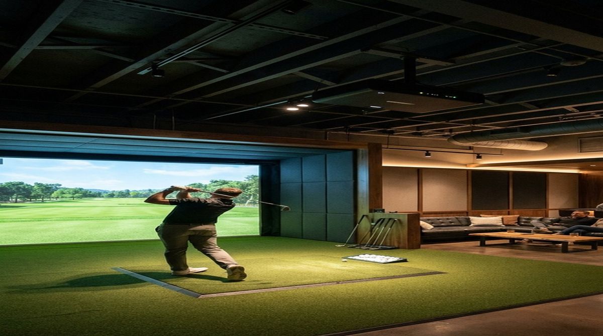
Every indoor golf simulator studio faces an optical paradox: your 4K laser projector requires near-total darkness (\(< 15\text{ lux}\) of stray ambient spill on the impact screen) to preserve deep black levels and vivid course contrast, while your golfer's eyes and high-speed optical launch monitor cameras require a bright, shadow-free hitting zone (\(1{,}200\) to \(2{,}000\text{ lux}\)) at the tee. Standard recessed garage ceiling can lights have wide \(90^{\circ}\) to \(110^{\circ}\) flood beam angles that scatter light directly onto the impact screen, destroying your contrast ratio and turning a $3,500 projector image into a washed-out gray haze.
By applying five exact trigonometric lighting formulas—governing Pin Spotlight Beam Spread Diameter, Inverse-Square Hitting Zone Illuminance, Ceiling Baffle Glare Cutoff Depth, and Flicker-Free PWM Camera Shutter Synchronization—you can project a razor-sharp 30-to-40-inch circle of light onto your hitting strip while keeping your impact screen pitch black. You can also verify your complete bay geometry using our interactive Golf Launch Monitor Fitter spatial tool.
Quick Optical Lighting Rules & Target Benchmarks:
- Optimal Pin Spotlight Beam Angle (\(\theta\)): Use a narrow \(15^{\circ}\) to \(24^{\circ}\) beam angle LED pin spot with a honeycomb louver snoot for 9-to-10-foot ceilings.
- Floor Light Puddle Diameter (\(D_{\text{beam}}\)): A \(19^{\circ}\) spotlight mounted at \(9.5\text{ ft}\) (\(114\text{ in}\)) produces a \(38.15\text{-inch}\) diameter light circle on the hitting mat, containing 100% of direct beam spill 8 feet away from the screen.
- Hitting Zone Illuminance (\(E_{\text{mat}}\)): Target \(1{,}500\text{ lux}\) at the ball using a \(1{,}200\text{-lumen}\) narrow-beam COB LED fixture, while keeping stray screen illuminance below \(12\text{ lux}\) (achieving a \(> 45:1\) effective ANSI contrast ratio).
- PWM Flicker Frequency Floor: High-speed optical launch monitors (Uneekor, Foresight, ProTee VX) shoot at \(3{,}000\text{ fps}\); use constant-current drivers or PWM dimming frequencies \(\ge 4{,}000\text{ Hz}\) to prevent dark banding on club impact replays.
1. Calculation 1: Pin Spotlight Beam Angle & Floor Puddle Diameter Formula
When a ceiling-mounted pin spotlight is aimed vertically downward (\(\phi = 0^{\circ}\) tilt) from ceiling mounting height \(H_{\text{mount}}\) above the hitting mat, the diameter of the illuminated light puddle on the turf \(D_{\text{beam}}\) is determined by the fixture's Full-Width Half-Maximum (FWHM) beam angle \(\theta\):
\[ D_{\text{beam}} = 2 \cdot H_{\text{mount}} \cdot \tan\left( \frac{\theta}{2} \right) \]Conversely, if you want to restrict your floor light puddle to a specific target diameter \(D_{\text{target}}\) (for example, \(36\text{ inches}\) to cover a \(18 \times 16\text{ in}\) hitting zone plus stance margins without spilling forward toward the impact screen), solve for the required fixture beam angle \(\theta\):
\[ \theta = 2 \cdot \arctan\left( \frac{D_{\text{target}}}{2 \cdot H_{\text{mount}}} \right) \]Worked Garage Example: Suppose your simulator ceiling height is \(H_{\text{mount}} = 9.5\text{ ft} = 114\text{ inches}\), and you install a \(19^{\circ}\) COB LED pin spotlight directly above the tee:
\[ D_{\text{beam}} = 2 \times 114\text{ in} \times \tan\left( 9.5^{\circ} \right) = 228 \times 0.16734 = 38.15\text{ inches} \quad (3.18\text{ ft diameter}) \]Because the tee is positioned \(10.0\text{ ft}\) (\(120\text{ in}\)) back from the impact screen, the forward edge of the \(38.15\text{-inch}\) beam circle terminates \(120 - 19.08 = 100.92\text{ inches}\) (\(8.41\text{ ft}\)) short of the screen. Compare that to a standard \(90^{\circ}\) recessed can light at the same \(114\text{-inch}\) height, which throws a \(228\text{-inch}\) (\(19\text{ ft}\)) puddle that washes directly halfway up your impact screen.
2. Calculation 2: Angled Rear-Offset Spotlight Elliptical Major Axis Math
To prevent a golfer's head or shoulders from casting a shadow over the golf ball at address, studio designers mount the pin spotlight \(d_{\text{rear}} = 18\text{ to }24\text{ inches}\) behind the tee line (away from the screen) and tilt the fixture forward toward the ball at incidence angle \(\alpha = \arctan(d_{\text{rear}} / H_{\text{mount}})\). This oblique projection stretches the circular beam into an ellipse whose longitudinal major axis \(L_{\text{major}}\) along the target line is:
\[ L_{\text{major}} = H_{\text{mount}} \cdot \left[ \tan\left( \alpha + \frac{\theta}{2} \right) - \tan\left( \alpha - \frac{\theta}{2} \right) \right] \]For \(H_{\text{mount}} = 114\text{ in}\), rear offset \(d_{\text{rear}} = 20\text{ in}\) (\(\alpha = \arctan(20/114) = 9.95^{\circ}\)), and a \(\theta = 15^{\circ}\) pin spot:
\[ L_{\text{major}} = 114 \times \left[ \tan\left( 17.45^{\circ} \right) - \tan\left( 2.45^{\circ} \right) \right] = 114 \times \left( 0.3143 - 0.0428 \right) = 30.95\text{ inches} \]3. Calculation 3: Ceiling Baffle Drop Depth for Glare Cutoff Protection
Even a narrow-beam spotlight emits secondary wide-angle lens glow outside its primary FWHM cone unless shielded by a cylindrical snoot, honeycomb louver, or ceiling acoustic baffle. To guarantee that zero direct light rays from a fixture mounted at distance \(X_{\text{screen}}\) from the impact screen can strike the top edge of the screen at height \(H_{\text{screen\_top}}\), install an acoustic ceiling baffle at distance \(x_{\text{baffle}}\) in front of the light with vertical drop depth \(d_{\text{baffle}}\):
\[ d_{\text{baffle}} \ge \frac{x_{\text{baffle}}}{X_{\text{screen}}} \cdot \left( H_{\text{mount}} - H_{\text{screen\_top}} \right) + L_{\text{lens\_recess}} \]For a spotlight at \(H_{\text{mount}} = 114\text{ in}\) located \(X_{\text{screen}} = 120\text{ in}\) from a screen whose top border sits at \(H_{\text{screen\_top}} = 102\text{ in}\), placing an acoustic baffle \(x_{\text{baffle}} = 24\text{ in}\) forward of the spotlight with a \(3.5\text{-inch}\) drop completely blocks any line-of-sight photon path to the upper screen canvas.
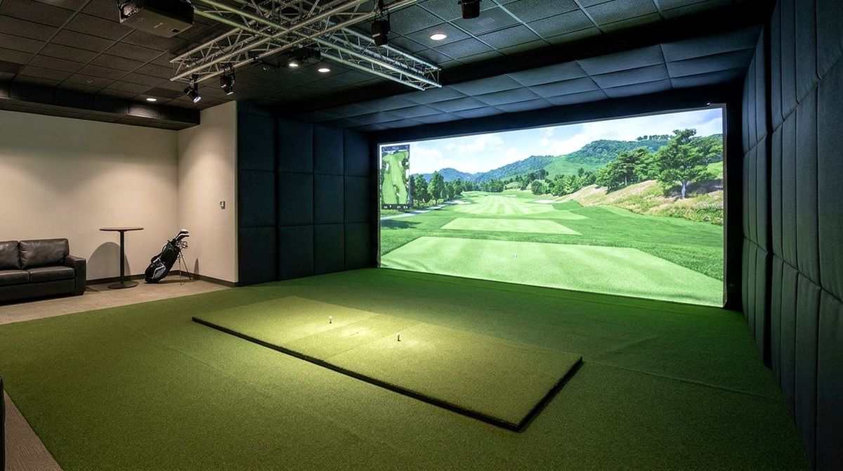
4. Pin Spotlight Beam Angle & Illuminance Reference Table
| Fixture Beam Angle (\(\theta\)) | Puddle Diameter at 9 ft (\(108\text{ in}\)) | Puddle Diameter at 10 ft (\(120\text{ in}\)) | Center Lux (800 lm LED) | Simulator Studio Application |
|---|---|---|---|---|
| \(10^{\circ}\) Ultra-Narrow Pin | \(18.9\text{ in}\) (\(1.57\text{ ft}\)) | \(21.0\text{ in}\) (\(1.75\text{ ft}\)) | \(3{,}450\text{ lux}\) | Single-spot ball highlight for floor-standing launch monitors. |
| \(15^{\circ}\) Narrow Spot | \(28.4\text{ in}\) (\(2.37\text{ ft}\)) | \(31.6\text{ in}\) (\(2.63\text{ ft}\)) | \(1{,}540\text{ lux}\) | Ideal for 10-ft ceilings & overhead camera hitting zones. |
| \(24^{\circ}\) Medium-Narrow Spot | \(45.9\text{ in}\) (\(3.83\text{ ft}\)) | \(51.0\text{ in}\) (\(4.25\text{ ft}\)) | \(605\text{ lux}\) | Full hitting strip + stance mat coverage on 8.5-to-9-ft ceilings. |
| \(36^{\circ}\) Wide Accent Flood | \(70.2\text{ in}\) (\(5.85\text{ ft}\)) | \(78.0\text{ in}\) (\(6.50\text{ ft}\)) | \(268\text{ lux}\) | Requires honeycomb louver + ceiling baffle to prevent screen washout. |
| \(90^{\circ}\) Standard Recessed Can | \(216.0\text{ in}\) (\(18.0\text{ ft}\)) | \(240.0\text{ in}\) (\(20.0\text{ ft}\)) | \(42\text{ lux}\) | Avoid; spills across impact screen and degrades contrast by 70%+. |
5. Calculation 4 & 5: Hitting Zone Lux & High-Speed Camera PWM Flicker Cutoff
Using the luminous intensity inverse-square law, the center-beam illuminance \(E_{\text{mat}}\) (in lux, or \(\text{lm/m}^{2}\)) delivered to the hitting mat by a spotlight of luminous flux \(\Phi\) (in lumens) and beam solid angle \(\Omega = 2\pi \left( 1 - \cos(\theta/2) \right)\) at throw distance \(d_{\text{throw}}\) (in meters) is:
\[ E_{\text{mat}} = \frac{\Phi}{2 \pi \cdot d_{\text{throw}}^{2} \cdot \left[ 1 - \cos\left( \frac{\theta}{2} \right) \right]} \]For an \(\Phi = 800\text{ lm}\) LED pin spot with a \(\theta = 15^{\circ}\) beam at \(d_{\text{throw}} = 2.74\text{ m}\) (\(9.0\text{ ft}\)), \(1 - \cos(7.5^{\circ}) = 0.008555\), yielding \(E_{\text{mat}} = 800 / (6.2832 \times 7.5076 \times 0.008555) = 1{,}982\text{ lux}\)—plenty of light for crisp clubhead tracking. Finally, ensure your LED driver's Pulse-Width Modulation (PWM) frequency \(f_{\text{PWM}}\) exceeds the camera shutter frame rate \(f_{\text{cam}}\) (\(3{,}000\text{ fps}\)) by at least \(1.33\times\) (\(f_{\text{PWM}} \ge 4{,}000\text{ Hz}\) or pure DC constant-current dimming) so your Uneekor Club Optix or ProTee VX impact video never exhibits rolling black flicker bars.
Design Your Complete Golf Simulator Room Geometry & Lighting Layout
Run your exact ceiling height, room depth, projector throw distance, and launch monitor offset through our interactive fitting calculator.
Open the Interactive Golf Simulator Room Fitter →