Golf Simulator Hitting Bay Width and Off-Center Tee Offset Formula: 5 Spatial Clearance Calculations for Dual-Handed Play
When designing a residential or commercial golf simulator studio, room width is frequently the most limiting physical dimension. While achieving sufficient ceiling height (9.5 to 10 feet) is straightforward in standard garages, accommodating the sweeping lateral arc of a 45.5-inch driver swing without striking side drywall requires meticulous architectural planning. Studio builders routinely confront the dilemma of whether their room can accommodate a true centered tee for both right-handed and left-handed golfers, or whether an off-center tee compromise is mandatory.
A centered tee setup delivers the most immersive simulator experience, as shots are launched directly toward the center of the impact screen. However, supporting centered play for righties and lefties demands a minimum room width of 14 to 15.5 feet. In narrower rooms (10 to 12.5 feet), shifting the tee laterally allows single-handed golfers to swing driver freely, but introduces aim line parallax angles that must be compensated for inside simulation software like GSPro or FSX Play. This engineering guide provides the exact trigonometric formulas to model driver swing arcs, calculate safe wall buffers, and configure off-center aim corrections.
Quick Answer & Key Spatial Takeaways:
- Minimum Centered Bay Width: Achieving a centered tee for dual-handed play requires a minimum clear width of 14.5 to 15.0 feet (\(4.42\text{ m}\text{ to }4.57\text{ m}\)) to maintain a 24-inch safety buffer behind both golfers.
- Minimum Single-Sided Bay Width: A dedicated right-handed or left-handed golfer can safely operate with an off-center tee in rooms as narrow as 10.0 to 11.0 feet (\(3.05\text{ m}\text{ to }3.35\text{ m}\)).
- Driver Swing Arc Radius: A standard 6-foot golfer swinging a 45.5-inch driver sweeps a physical radius of 5.5 to 6.0 feet from the ball to the maximum backswing clubhead apex.
- Off-Center Aim Line Correction: Shifting the tee 18 inches off-center on a 10-foot ball-to-screen throw creates an 8.53° azimuth angle that must be corrected in simulator software calibration.
- Interactive Fitter Tool: Verify your exact studio dimensions and screen aspect ratios using the Golf Launch Monitor Fitter spatial calculator.
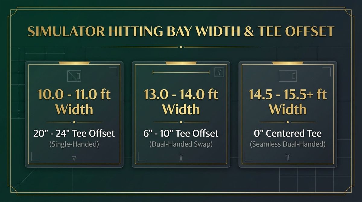
Figure 1: Overhead schematic diagram showing centered vs off-center tee positions, driver swing envelopes, and side wall safety buffers.
1. The Driver Swing Arc Envelope and Minimum Centered Width Formula
A golf swing is not planar; it forms an inclined rotational cone. The widest point of lateral wall clearance occurs during the peak of the backswing and the completion of the follow-through. For a golfer of height \(H_{\text{golfer}}\) using a driver of shaft length \(L_{\text{club}}\), the dynamic swing radius \(R_{\text{swing}}\) extending rearward from the tee is:
\[ R_{\text{swing}} = (0.55 \times H_{\text{golfer}}) + (L_{\text{club}} \times \cos\theta_{\text{lie}}) \]For a typical 6-foot (72-inch) golfer with a 45.5-inch driver and 58° lie angle:
\[ R_{\text{swing}} = (0.55 \times 72\text{ in}) + (45.5\text{ in} \times \cos(58^\circ)) = 39.6\text{ in} + 24.1\text{ in} = 63.7\text{ in} \quad (5.31\text{ feet}) \]To calculate the minimum total room width \(W_{\text{center},\min}\) required to place the tee at the absolute center of the bay while allowing both right-handed and left-handed players to swing driver with a safety wall clearance buffer \(C_{\text{wall}}\) (recommended 24 inches):
\[ W_{\text{center},\min} = 2 \times (R_{\text{swing}} + C_{\text{wall}}) \] \[ W_{\text{center},\min} = 2 \times (63.7\text{ in} + 24.0\text{ in}) = 2 \times 87.7\text{ in} = 175.4\text{ inches} \quad (14.62\text{ feet}) \]If your room measures less than 14.62 feet in clear width, attempting to center the tee will leave less than 24 inches of clearance behind the golfer's backswing, creating psychological tension and the severe risk of drywall impact.
2. Off-Center Tee Lateral Offset Calculation Formula
When room width is constrained to 10.5 to 13.0 feet, the tee must be shifted toward the non-swinging wall. For a right-handed golfer, the ball is shifted to the right of room centerline, allowing the golfer's body to occupy the center while preserving the 24-inch rear buffer against the left wall.
The maximum safe lateral offset \(\Delta X_{\text{tee}}\) from the center of the room is calculated as:
\[ \Delta X_{\text{tee}} = \frac{W_{\text{bay}}}{2} - (R_{\text{swing}} + C_{\text{wall}}) \]Consider a standard single-car garage bay measuring 11.5 feet (138 inches) wide:
\[ \Delta X_{\text{tee}} = \frac{138\text{ in}}{2} - (63.7\text{ in} + 24.0\text{ in}) = 69.0\text{ in} - 87.7\text{ in} = -18.7\text{ inches} \]This negative result indicates that the tee must be positioned exactly 18.7 inches to the right of room center, placing the tee 50.3 inches from the right wall and leaving 87.7 inches between the tee and the left wall for the golfer's stance and backswing arc.
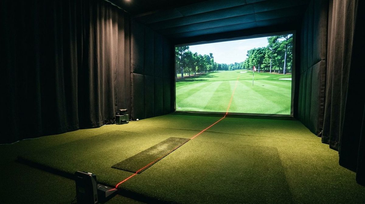
Figure 2: Parallax aim line angle correction and impact screen target centering geometry.
3. Software Aim Line Parallax and Azimuth Correction Angle
When the tee is placed off-center, launching a shot straight ahead causes the ball to strike the impact screen offset from center. If the software assumes a centered tee, a shot that hits 18 inches right of screen center will be registered as a push or block. To ensure accurate course rendering, simulation software requires an aim line azimuth angle correction \(\alpha_{\text{aim}}\):
\[ \alpha_{\text{aim}} = \arctan\left( \frac{\Delta X_{\text{tee}}}{D_{\text{screen}}} \right) \]Where \(D_{\text{screen}}\) is the distance from the tee to the impact screen (typically 10 feet or 120 inches). For an 18.7-inch offset:
\[ \alpha_{\text{aim}} = \arctan\left( \frac{18.7\text{ in}}{120\text{ in}} \right) = \arctan(0.1558) = 8.85^\circ \]By entering an 8.85° horizontal target offset inside GSPro or FSX, the in-game target line is dynamically aligned directly with your physical tee position, restoring true aiming physics.
4. Spatial Clearance Comparison Matrix across Common Bay Widths
| Room Clear Width | Tee Configuration | Rear Wall Buffer | Dual-Handed Viability | Recommended Launch Monitor |
|---|---|---|---|---|
| 10.0 – 11.0 ft (3.05 – 3.35m) | Extreme Off-Center (20"–24" offset) | 18" – 22" | Single-Handed Only | Floor Photometric (GC3, EYE MINI) |
| 11.5 – 12.5 ft (3.50 – 3.81m) | Moderate Off-Center (12"–18" offset) | 24" – 28" | Single-Handed Preferred | Floor Photometric or Trackman iO |
| 13.0 – 14.0 ft (3.96 – 4.27m) | Slight Off-Center (6"–10" offset) | 28" – 32" | Dual-Handed with Swapping | Overhead AI Vision (ProTee VX) |
| 14.5 – 15.5+ ft (4.42 – 4.72m) | True Centered Tee (0" offset) | 24"+ Both Sides | Seamless Dual-Handed Play | Overhead System (ProTee VX, EYE XO2) |
5. Follow-Through Wall Clearance Safety Factor
The follow-through arc extends forward and upward toward the impact screen. To ensure that high-velocity follow-throughs on aggressive driver strikes do not impact side safety padding, calculate the safety factor index \(S_{\text{clear}}\):
\[ S_{\text{clear}} = \frac{D_{\text{wall,forward}} - R_{\text{follow}}}{R_{\text{follow}}} \times 100\% \]A safety factor \(S_{\text{clear}} \ge 25\%\) is mandatory to prevent accidental wall contact. For detailed spatial modeling across custom garage floorplans, use the Golf Launch Monitor Fitter tool.
6. Standard Operating Verification & Bay Layout Audit Checklist
- Measure the clear bay width at 3 distinct heights (floor, 4 feet, and 7 feet) to detect drywall framing bows or baseboard intrusions.
- Perform a slow-motion test swing with a 45.5-inch driver while a spotter measures the minimum clearance to the rear side wall.
- Mark the physical tee position on the hitting mat with high-contrast white tape and measure the exact distance to the impact screen.
- Enter the measured lateral tee offset (\(\Delta X_{\text{tee}}\)) into simulator software settings and calibrate the projector alignment grid.
- Hit 5 test mid-iron shots along the corrected aim line to confirm shot trajectory renders dead-center on the projected virtual fairway.
Model Your Simulator Room Dimensions
Calculate minimum bay width, ceiling heights, projector throw ratios, and screen aspect ratios for your exact garage footprint.
Launch Simulator Spatial Calculator